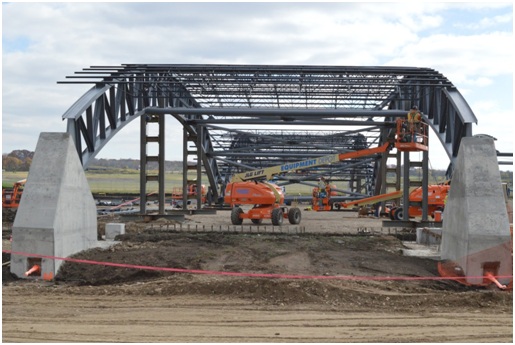
Form plus function almost always results in a great design. Architectural design in addition to engineering design represents each of the variables in the equation for a successful design solution. The architectural aspect of a curved beam design achieves ideal appearance and functionality. A design that has been well engineered produces an efficient and capable performance solution.
Steel beams are a very popular structural building component. They are used as both columns and beams to resist self-weight, gravity, wind, seismic, axial compression, shear and bending moment forces in and on buildings and similar structures. Larger beams are able to support larger loads for longer distances. However, when you need support for a curving slab edge or something to support an elevated roof or entryway across a large unobstructed space, incorporating a curved beam design may be the solution you need.
Curved in either the X-X axis, Y-Y axis or at a custom diagonal orientation known as off-axis (in degrees), the procedure for curving steel beams can prove to be a very versatile engineering and or architectural solution. Since structural design mostly focuses on straight beams, engineering a curved beam design for structural use is recommended to be done by a licensed structural engineer with experience in designing curved beams. Circular, parabolic and even elliptical arches or cantilevers can be designed for, but the procedure for designing steel beams to perform successfully when rolled to these shapes will differ slightly from the standard approach.
Typically an arch or curved beam in elevation will be sized using some of the same equations and checks as a simply supported straight beam. Differences will be found in the way axial compressive forces and bending moments are calculated due to a height component of the curve or arch (in elevation). Load cases that typically produce maximum shear and bending moment forces in straight beams will also differ from load cases used to analyze arched beams. Because arches will experience axial stress as well as bending moments, the curved beam design procedure is different than that of a straight beam subject to shear and bending moments. Pertaining to arches, more important than the stiffness of the member is the stiffness of its fixed supports. Supports must be paid special attention to as they must not be allowed to move laterally or allow significant rotation at the ends of the member. Too much movement or rotation can cause the stresses in the member to rearrange and risk collapse. Overall, the size of the arch and beam in use should be checked for lateral torsional buckling under load as you would a normal beam of extensive length. Due to the curve of the arch, if exposed to wind loads, you must also take into account any opposing pressure or suction loads caused by the effects of lift on the curved faces of the arch. Effective lengths for additional lateral support may need to be considered for arch trusses used in stadium or bridge construction for example. For beams curved in plan that are used to support floor slabs or slab edges, accommodations in the design of the structure and connections must be made to combat effects of natural torsion or rotation of the beam while under load.
Besides ensuring that the design engineering of an arch or curved beam will perform safely for its intended application, the schematic design and dimensions must be drawn and modeled correctly for a specialty bender roller company to utilize for accurate reproduction. Dimensions indicative of any round or circular arc are known as either a radius or diameter. Radii or diameters are preferred to be taken from the inside of the curved beam for checking purposes but are commonly drawn to the centerline of beams. Any multi-radius curves that are drawn as a true ellipse or parabola should specify that it is drawn as such and should indicate extents of height and width. If a truly organic curve is required, a sequence of circular arc segments must be drawn end-to-end as tangent to each other as possible with a radius and arc length specified for each arc segment. This sequence of arcs is a larger interval representation of the constant radius change of a true ellipse or parabola. The material, whether curved or straight, on the end of an arc segment, must be specified as extra for fabrication or tangent to the arc. With our in-house drafting and modeling capabilities, Chicago Metal Rolled Products can work closely with you to aesthetically design, modify or convert your conceptual or construction drawings into schematics and templates that accurately communicate your requirements to our shop for quick and successful manufacturing.


